How to write and test portable I/O driver source code
One primary purpose with IOTester is to enable programmers
to write, use, and test embedded I/O driver software on the PC.
The goal is that the C source code itself can be moved around, and reused in
all places where the I/O driver chip can be connected.
Logical operation in C source > Physical operation on I/O register
The I/O driver source code should be written with the goal that the source code itself become portable across embedded processor systems. The I/O driver source code must be the same, independent of any intrinsic syntax for I/O access used by the compiler vendor, independent of the target processor type, and independent of whether the source code is compiled for a target processor system, OR for use on a PC with the IOTester tool.
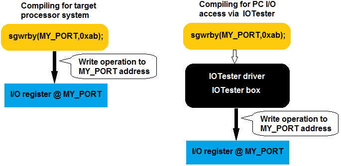
The same C syntax is used for I/O access, both in different target processor systems and on
the PC using IOTester.
Design for portability and source code reuse
One easy method to achieve C source code portability for I/O drivers is to use the portable SG I/O syntax for basic low-level RD, WR, AND, OR access operations on the target I/O hardware.
The SG method is a HAL layer method to create I/O driver source code portability, and is used, for instance, in driver source code for all the display controllers supported by RAMTEX display driver libraries.
// A symbolic name (MY_PORT) for the I/O register maps to a
// complete definition of how to access the I/O register.
// All processor hardware (and compiler) specific knowledge is encapsulated in
// in a separate header file (the only target system specific part).

#include <sgio.h> // Defines hardware and access method
// ...
// I/O access functions. Do Write, Read, And, Or, operations on external I/O chip
char val = 0x12;
sgwrby( MY_PORT, val);   // Bus /WR clock
val = sgrdby(MY_PORT);   // Bus /RD clock
sgandby(MY_PORT, val);   // Bus /RD, /WR clock
sgorby( MY_PORT, val);   // Bus /RD, /WR clock
The source code above uses the SG syntax for I/O access. The source code portability is created by encapsulating all knowledge about the specific bus hardware in the specific target system and any compiler intrinsic syntax for I/O register addressing behind a symbolic name for the I/O register and inside a few "standardized" (macro) functions. With most compilers and processor types on the market the SG method can assure C source code portability can achieved without any machine code or runtime overhead.
The symbolic name for the I/O register (MY_PORT) maps to a complete definition of how to access a specific register in a specific target system. This information is included via a target hardware-specific header. So the code is moved to new hardware, only the few I/O register address definitions in this header need to be updated.
The only source code differences between compiling for the target processor system and compiling for PC I/O access via IOTester, are therefore the few I/O register address definitions in a header file.